Page 1 of 1
how to connect radiator fan temperature sensors?
Posted: Thu Aug 03, 2023 3:12 pm
by alebal
after putting the engine back in, my mechanic and I connected the radiator fan... and we probably got a wrong cable because the temperature sensor on the cylinder exploded...
there are two sensors, one on the cylinder and one on the radiator, my bike's electrical system has been compromised for almost 40 years and now all the connectors are the same, and understanding where each one goes is impossible.
now it's not clear how we did it, but the fan is constantly on.
I'm waiting for a new sensor from ebay, but before I blow up a second one, can you help me understand how they are connected?
Re: how to connect radiator fan temperature sensors?
Posted: Thu Aug 03, 2023 5:38 pm
by sgtcall
Start by reading these threads.
viewtopic.php?f=81&t=14554
viewtopic.php?p=229973#p229973
viewtopic.php?f=81&t=14536
hillsy v2 wrote: ↑Wed Aug 02, 2023 8:04 pm
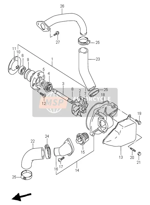
Pretty sure the fan switch is on the back of the radiator (#30)
And thermostat is in the water pump housing (#15):
Re: how to connect radiator fan temperature sensors?
Posted: Tue Aug 08, 2023 6:48 pm
by alebal
so... tomorrow I'll try to connect 30 to the fan and see what happens...
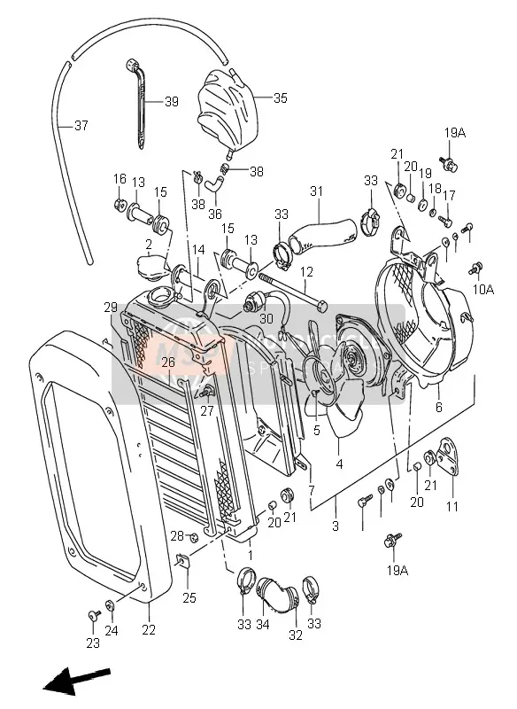
but a doubt remains, if 30 is the fan switch, what did I blow up? I blew up the 44...

Re: how to connect radiator fan temperature sensors?
Posted: Tue Aug 08, 2023 10:09 pm
by Herb
alebal wrote: ↑Tue Aug 08, 2023 6:48 pm
so... tomorrow I'll try to connect 30 to the fan and see what happens...
but a doubt remains, if 30 is the fan switch, what did I blow up? I blew up the 44...
Temp sending unit...
https://www.suzukipartshouse.com/oempar ... head-front
The OEM parts fiches are a wealth of information.
Not sure where to find the wiring diagram for the 700. There is one for the 800 in the drop box and it is color coded fro the wires, it might point you to the correct direction for proper wiring.
Re: how to connect radiator fan temperature sensors?
Posted: Wed Aug 09, 2023 6:08 pm
by alebal
I have some diagrams...

the problem is that I don't understand them... the electrical part is not my favourite.
I also have this,

where the wires of the sensor that I exploded seem to go upwards...
Could it be that the sensor on the radiator turns the fan on and off, the other sensor turns on the alarm light? (which I don't have...)
Re: how to connect radiator fan temperature sensors?
Posted: Wed Aug 09, 2023 6:26 pm
by hillsy v2
alebal wrote: ↑Wed Aug 09, 2023 6:08 pm
I have some diagrams...
the problem is that I don't understand them... the electrical part is not my favourite.
So the fan is powered +ve when the ignition switch is turned on (orange wire) - it is then grounded via the B, B/W wire when the fan switch activates and completes the circuit - turning the fan on.
The water temperature gauge is not connected to that circuit - you may not even have a gauge / light?
Re: how to connect radiator fan temperature sensors?
Posted: Wed Aug 09, 2023 6:39 pm
by Herb
Your wiring diagram isn't complete in the post so it is hard to tell.
On a wiring diagram the wire colors are indicated by 1 or 2 letters. the first letter tells the color of the wire the second tells the color of a tracer. B/W would be black with a white tracer.
follow the wires from the part to the power, a ground, or another part. Not sure of your system but the temp sensor for the warning light would probably have a wire from the light, power, and a ground wire to a common ground. when it sensed a possible over temp it would provide a ground for the light.
As for the fan switch it would, probably, have a power wire from the fan and a ground wire, when it reaches a certain temp it would provide a ground for the fan power to turn the fan on.
The reason the fan is on all the time is probably because the power goes to the fan then to the switch and when you hooked the wires up you accidently hooked the power from the fan to the ground wire. Try switching the wires at the switch. You can use the wiring diagram and the wire colors to tell which wires go where. Most of the time am Orange/White (O/W) wire will connect to another O/W wire or dead end at a switch, a light, a part, etc. Since I don't have a full wiring diagram I can't provide much more guidence.
Go to the drop box and download then print the 800 color coded wiring diagram. Then compare the diagram you have to it and get a general idea of the way the diagram works. I think that it gives a legend of what the wire colors mean.
I believe that Suzuki probably kept to the same circuits/wire colors except for any additional parts/items they added. Example, the 1400 wiring diagram is the same from 87 on except for the change of the ignition box, the addition of the boost sensor, the wiring change so that the carbs can be primed by leaving the clutch out and pushing the start button. The basics of the ignition system, the lighting, the fuses, etc are all the same.